
One of my issues with building instruments during the winter is that my garage is not heated. I have an electric baseboard heater mounted to the front of my workbench. This keeps my hands and front warm, but it doesn’t do much for my feet or any of my materials. I have a little ceramic heater that I sometimes use toward that end. But that’s not even the real problem. The real problem is that it’s too cold to apply finishes to my guitar necks. I have on occasion used my little ceramic heater to dry necks. Usually by just putting it under where the necks are hanging. That works okay, but the heat dissipates quickly and the heater has to be on all the time. If you forget to turn it off, as I did for a couple weeks one time, the electric bill gets pretty extraordinary.
At one point, I used my kids playhouse as a paint booth. It’s small enough that the whole thing stayed warm. This gave me an idea to have a small area in my garage that I could keep warm enough for curing finishes, without attempting to heat the whole garage. When they started getting rid of tall metal cabinets at work, that seemed like the perfect thing. I could put the heater on the bottom and hang necks from the top. The only issue was, with a space that small, even my small ceramic heater would get it way too hot (and it would still be running all the time… driving up the electric bill.) So I decided that what I needed to do was install a thermostat in the cabinet that would control my heater. Then I could keep it at a constant 70 degrees.
You could also use this for an electric heater in a greenhouse (or in the summer, a fan to keep it from getting too hot). Baseboard heaters in the basement?
This is how I put that together.
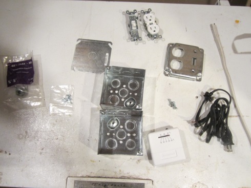
This is what I started out with. This wasn’t quite right. I didn’t realize that thermostats were rated for only 24 volts. So I started with the wrong thermostat and mounting plate for that thermostat. If you’re going to reproduce this, here’s what you’ll need.
- 2 2-gang electrical boxes (or a 4 gang should work if you can find one)
- 1 switch
- 1 recepticle
- wire (I used a leftover piece of 14 gauge romex)
- power cord (Mine was saved from a broken appliance)
- 2 small screws and nuts
- 1 combination connector
- switch/recepticle plate
- outlet plate (with rectangular opening)
- LINE VOLTAGE thermostat
First knock out a couple of the holes that will line up when the boxes are screwed together.

Then using a couple small screws and nuts, attach the boxes. (There are holes in mine already so I just had to slide the screws through and tighten them up)

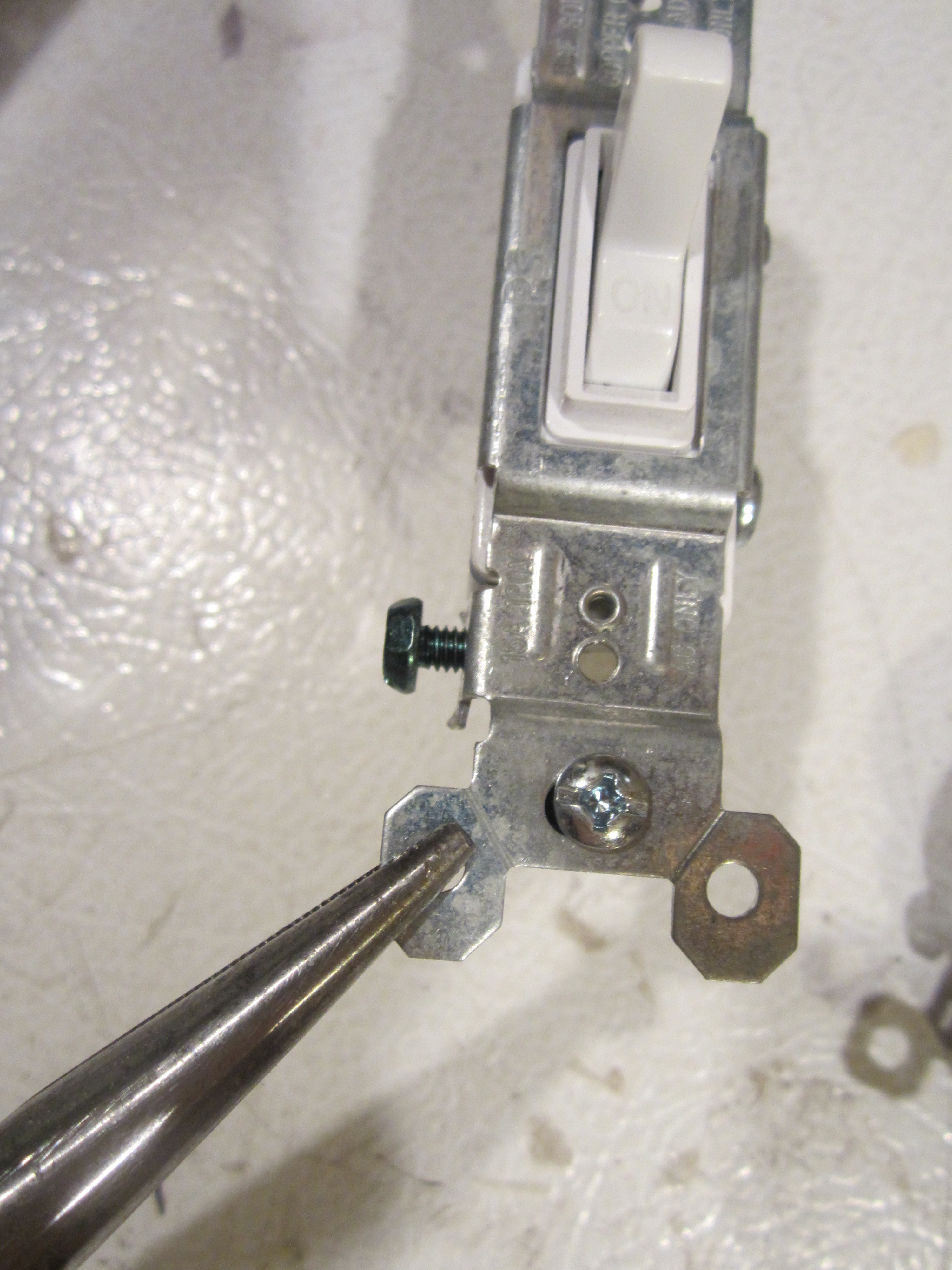
Using a pliers, break off the tops on the switch and receptacle.
Knock out a hole in what will now be the bottom of the assembly and install your combination connector.

Separate the sides of the cord and strip the end of the wires. Feed it through the clamp on the combination connector. Make sure you feed enough in to attach to the switch and receptacle (better to have extra than not enough)
My power cord wasn’t quite thick enough for the clamp to get a good grip on, so I tied a knot so it couldn’t pull out.

Attach the cord as show in this wiring diagram. Run the hot side (small prong on the plug) to the switch.

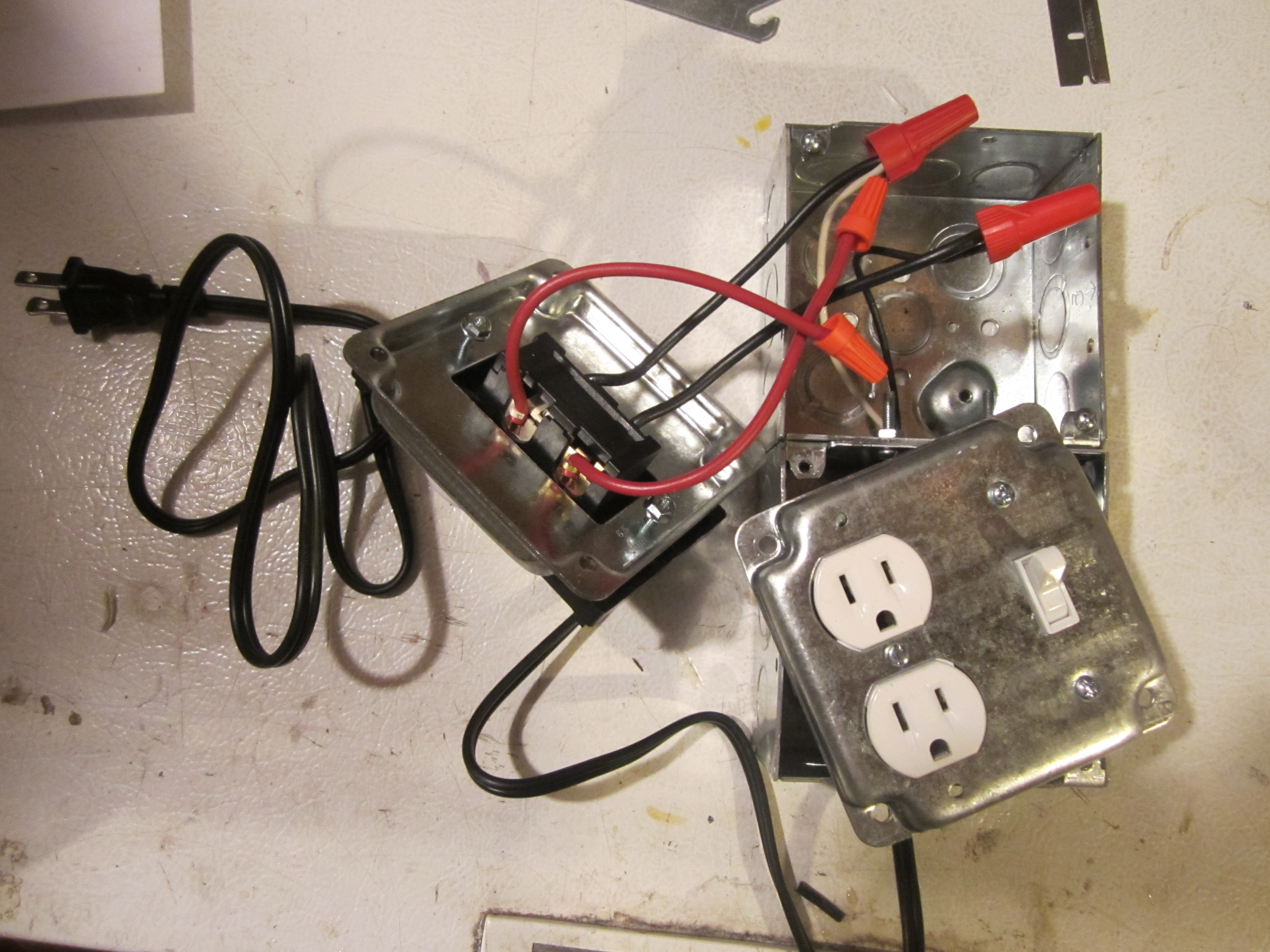
Attach the switch and receptacle to the cover plate, then attach wires to go to the thermostat. Feed those through the hole between the two boxes.

The cover plate comes with screws and nuts. I put in the center screw on the receptacle and forgot about those until I had the whole thing buttoned up and noticed the empty holes on the plate.

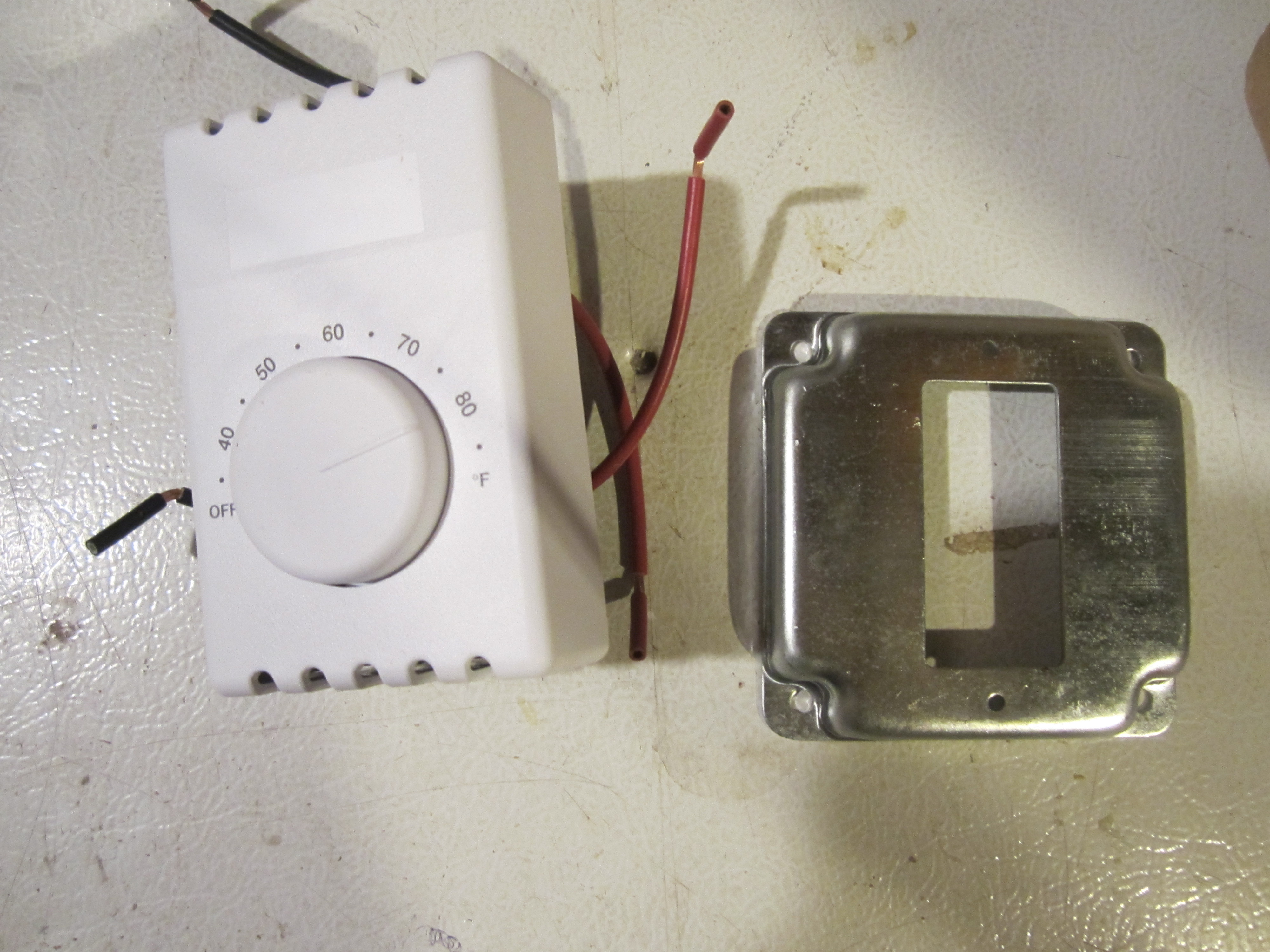
Here is the correct line voltage thermostat and plate. (Actually this is a double pole thermostat and I only needed a single pole, but that’s all they had)
Take a look at the wiring diagram that comes with your thermostat. If you have a single pole, it should just have two wires. If you have a double pole like this one, you’ll have to look at the diagram to see which ones you’re supposed to use. Feed the wires through the plate, install the screws and tighten on the nuts that come with the plate.

Connect the wires using tight fitting electrical caps. Cap any unused wires as well.
Now just screw the covers on. I had to elongate the holes on mine to get both plates to fit next to each other. I just used a drill.

Now all you have to do is plug it in and test it. I tested it by plugging my heater into it and setting it directly in front. When the heater brought the temp up to 70, it the thermostat shut it off. Perfect! Now I just need to get it installed in my cabinet.

The switch on this one actually ends up being superfluous because as you can see in this picture, the line voltage thermostat has an “OFF” setting. I’m not sure if all voltage line thermostats have this setting. I’m guessing they do in which case you can eliminate the switch entirely. I kind of wish I had picked up a lighted switch, so I would have a visual reminder that the power was on and wouldn’t accidentally leave the heater running when it wasn’t necessary. Maybe later.

April 8th, 2013 at 9:15 pm
This is perfect, I have a Kerosene Salamander and I use it all the time for my single car garage, however im constantly pluggin it in and unplugging it when it warms up, I just really want it to stay at one temp…
May 23rd, 2014 at 4:51 am
Good info. Lucky me I recently found your blog by chance (stumbleupon).
I have bookmarked it for later!
December 20th, 2014 at 6:17 am
Couldn’t you use an electronic baseboard timer to control timing too?
February 6th, 2015 at 9:26 pm
The picture with the switch and plug shows you are switching the neutral circuit. That is a no-no.
February 6th, 2015 at 9:30 pm
…or if you are actually switching the hot wire, then you are connecting it to the wrong side of the receptacle. The wide (left) side is the neutral. Wiring it backwards is very dangerous.
December 9th, 2015 at 8:43 pm
Are you talking about the diagram I made? I think perhaps I just color coded it backwards. Is that what you mean?
October 24th, 2015 at 2:49 pm
If I wanted to try something like this to keep my chicken’s water from freezing, can the thermostat (that controls the heater being on or off ) be activated by a remote sensor that would be measuring the temperature of the water and not the ambient air? If so, do you have a reccommendation? Something that could turn on the heater when the water temp is around 35 deg and off when it reaches say 45 would be perfect.
December 9th, 2015 at 8:43 pm
I’ll be posting a chicken water heater sometime in the near future.